Learning embedded Rust with the nRF24L01+ 2.4 Ghz
I’ve been meaning to learn a system programming language and learn about embedded programming. I opted for Rust due to its focus on safety, great support for WebAssembly and helpful and growing community. It seems like a promising language and a great fit for a beginner with a JavaScript or TypeScript background.
Discovery
I started by going through the Discovery book, which is an introduction to embedded programming in Rust. I can not recommend this book enough as it’s easy to grok and a fun way to get started.
The book uses the STM32F3DISCOVERY development board, which is relatively cheap for what it offers. The exercises in the book will introduce you to working with many of its components such as the magnetometer, accelerometer, gyroscope and LEDs.
nRF24L01+
Upon finishing the aforementioned book, there’s a list a of suggestions on what you might want to explore next. I opted for wireless communication.
One of the more popular consumer devices for this seems to be the nRF24L01+. It has a version with an internal and external antenna, the latter having a much greater range — claiming up to 800–1000 meters. I ended up getting them both, as they’re quite cheap.
I wanted to communicate between the embedded device and my computer, so I ended up ordering a third party device that should have allowed me to transmit or receive the data sent by the The NRF24L01 to USB modulenRF24L01+ over USB.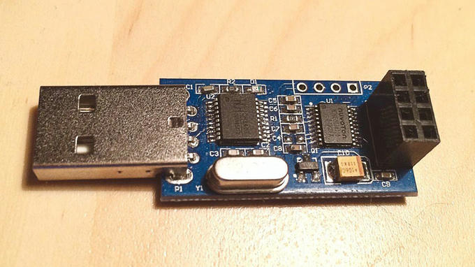
It didn’t entirely pan out the way I thought it would. Supposedly, one needs to short the GND and SWM pin on the module in order to switch it from receive to transmit and vice versa.
I contacted the manufacturer of said module and they were kind enough to send the code and schematic. The comments were all in Chinese, but I managed to extract the settings by referencing the registers in the code with the manufacturer’s documentation for the nRF24L01+. Here’s a small snippet:
void NRF24L01_TX_Mode(void)
{
	NRF24L01_CE_LOW;

	NRF24L01_Write_Buf(NRF_WRITE_REG+RX_ADDR_P0,(u8*)RX_ADDRESS,RX_ADR_WIDTH);//设置TX节点地址,主要为了使能ACK
	NRF24L01_Write_Reg(NRF_WRITE_REG+EN_AA,0x01);     //使能通道0的自动应答
	NRF24L01_Write_Reg(NRF_WRITE_REG+EN_RXADDR,0x01); //使能通道0的接收地址
	NRF24L01_Write_Reg(NRF_WRITE_REG+SETUP_RETR,0x1a);//设置自动重发间隔时间:500us + 86us;最大自动重发次数:10次
	NRF24L01_Write_Reg(NRF_WRITE_REG+RF_CH,40);       //设置RF通道为40
	NRF24L01_Write_Reg(NRF_WRITE_REG+RF_SETUP,0x0f);  //设置TX发射参数,0db增益,2Mbps,低噪声增益开启
	NRF24L01_Write_Reg(NRF_WRITE_REG+CONFIG,0x0e);    //配置基本工作模式的参数;PWR_UP,EN_CRC,16BIT_CRC,

	NRF24L01_CE_HIGH;
	delay_10us(5);
}
To my surprise, the included schematic and firmware I was sent mentions the use of the STM8S103F MCU, while the chip I received is fitted with the N76E003AT20 MCU. I was told that this simply was a newer module and everything should still work — except it didn’t. Considering that the TX and RX addresses were hard coded, they might simply differ on the module I received. Instead of going through the billions of potential configurations or learning about logic analyzers, I decided to back out of this rabbit hole and use an Arduino instead.
Connecting the devices
To connect either of the two to the development board, you’ll need at least 7 female to female jumper cables, as the device uses SPI to communicate.
When connecting the device, you’ll become accustomed to looking through the datasheet of the board. To find out which pins on the board will fit our cables, we’ll have to look at 6.12, Extension Connectors of the user manual for the STM32F3DISCOVERY. I ended up picking following pins:
Do not connect the device to 5V on the STM32F3DISCOVERY, as it is only rated for 3V and might be damaged otherwise.
| Color | Pin | Pinout | Base address |
|---|---|---|---|
| Red | 3V | VCC | N/A |
| Black | GND | GND | N/A |
| Purple | PA6 | MISO | 0x4800 0000 - 0x4800 03FF |
| Blue | PA7 | MOSI | 0x4800 0000 - 0x4800 03FF |
| Green | PA5 | SCK | 0x4800 0000 - 0x4800 03FF |
| Yellow | PB2 | CE | 0x4800 0400 - 0x4800 07FF |
| Orange | PB0 | CSN | 0x4800 1000 - 0x4800 17FF |
Transmitting
Before we end up looking at the code, I can not stress this enough, in order to save you the headache of not receiving data, make sure that:
- The RX and TX address differ
- The RX and TX addresses are the same on both devices
- The payload type or size matches on both devices
fn nrf24_rx() -> ! {
    // Cortex and device peripherals
    let mut cp = cortex_m::Peripherals::take().unwrap();
    let dp = stm32f30x::Peripherals::take().unwrap();

    // Instrumentation Trace Macrocell for debugging
    // See: https://blog.japaric.io/itm/
    let stim = &mut cp.ITM.stim[0];

    // Split RCC and Flash into different functionalities
    // See: https://blog.japaric.io/brave-new-io/#freezing-the-clock-configuration
    let mut flash = dp.FLASH.constrain();
    let mut rcc = dp.RCC.constrain();

    // Split into independent pins and registers
    let mut gpioa = dp.GPIOA.split(&mut rcc.ahb);
    let mut gpiob = dp.GPIOB.split(&mut rcc.ahb);

    // LEDs
    let mut leds = Leds::new(dp.GPIOE.split(&mut rcc.ahb));

    // Clocks
    let clocks = rcc.cfgr.freeze(&mut flash.acr);

    // Delays
    let mut delay = Delay::new(cp.SYST, clocks);

    // Configure pins
    let radio_ce = gpiob
        .pb2
        .into_push_pull_output(&mut gpiob.moder, &mut gpiob.otyper);
    let radio_csn = gpiob
        .pb0
        .into_push_pull_output(&mut gpiob.moder, &mut gpiob.otyper);

    let radio_sck = gpioa.pa5.into_af5(&mut gpioa.moder, &mut gpioa.afrl);
    let radio_miso = gpioa.pa6.into_af5(&mut gpioa.moder, &mut gpioa.afrl);
    let radio_mosi = gpioa.pa7.into_af5(&mut gpioa.moder, &mut gpioa.afrl);

    let radio_spi = f3::hal::spi::Spi::spi1(
        dp.SPI1,
        (radio_sck, radio_miso, radio_mosi),
        embedded_hal::spi::Mode {
            polarity: embedded_hal::spi::Polarity::IdleLow,
            phase: embedded_hal::spi::Phase::CaptureOnFirstTransition,
        },
        1.mhz(),
        clocks,
        &mut rcc.apb2,
    );

    let mut radio = NRF24L01::new(radio_ce, radio_csn, radio_spi).unwrap();

    let addr: [u8; 5] = [0x22, 0x22, 0x22, 0x22, 0x22];

    radio.set_frequency(100).unwrap();
    radio.set_auto_retransmit(0, 0).unwrap();
    radio.set_crc(Some(CrcMode::TwoBytes)).unwrap();
    radio.set_rf(DataRate::R250Kbps, 1).unwrap();
    radio
        .set_auto_ack(&[false, false, false, false, false, false])
        .unwrap();
    radio
        .set_pipes_rx_enable(&[true, false, false, false, false, false])
        .unwrap();
    radio
        .set_pipes_rx_lengths(&[None, Some(1), Some(1), Some(1), Some(1), Some(1)])
        .unwrap();
    radio.set_tx_addr(&addr).unwrap();
    radio.set_rx_addr(0, &addr).unwrap();
    radio.flush_rx().unwrap();
    radio.flush_tx().unwrap();

    delay.delay_ms(10u8);

    // Transfer into RX
    let mut radio = radio.rx().unwrap();

    // Debug configuration
    iprintln!(stim, "\n");
    iprintln!(stim, "AutoAck: {:?}", radio.get_auto_ack().unwrap());
    iprintln!(stim, "Register: {:?}", radio.get_address_width().unwrap());
    iprintln!(stim, "Frequency: {:?}", radio.get_frequency().unwrap());

    delay.delay_us(130u8);

    loop {
        if let Some(pipe) = radio.can_read().unwrap() {
            iprintln!(stim, "Reading from pipe: {}", pipe);
            let payload = radio.read();
            match payload {
                Ok(p) => {
                   iprintln!(stim, "Payload received: {:?}", p.as_ref());
                    leds[Direction::West].on();
                }
                Err(_) => {
                    iprintln!(stim, "Could not read payload");
                    leds[Direction::North].on();
                }
            }
        }
        leds[Direction::West].off();
        leds[Direction::North].off();
    }
}
Closing words
I hope you enjoyed reading this journey so far and that it was of interest. If you have any additions or tips, please do reach out via twitter or e-mail.